Choosing the right Carbon Fiber Square Rod begins with understanding the job it must perform. A lightweight frame, robotic arm, camera mount, or custom guide may require different properties. Start with the expected load, span, vibration, and temperature range. Do not choose by appearance alone. A glossy surface cannot reveal internal fiber alignment.
In practical engineering work, dimensions matter immediately. Measure the required length and check the square profile carefully. A 20 mm rod may fit one joint but fail inside another connector. Compare wall thickness, resin quality, surface finish, and allowable tolerances. Carbon fiber offers excellent stiffness, yet it can crack under impact or crushing pressure. That detail is easy to overlook. Consider how fasteners will contact the rod. Sharp bolts can create local damage. Bonded joints may distribute stress more evenly, but adhesive selection and curing conditions still matter.
Reliable selection also depends on evidence. Ask suppliers for fiber orientation, mechanical data, manufacturing standards, and inspection records. Test a sample when the application carries meaningful loads. Simple checks can expose problems: inspect straightness, compare weight, and examine cut edges under strong light. I have seen specifications look convincing while the actual fit was disappointing. That is a useful reminder: published values may come from controlled laboratory conditions. Real assemblies include holes, joints, weather, and repeated movement. Choose with those details in mind, and document your assumptions before ordering. The best Carbon Fiber Square Rod is not always the strongest option. It is the one that matches the complete application safely and consistently.
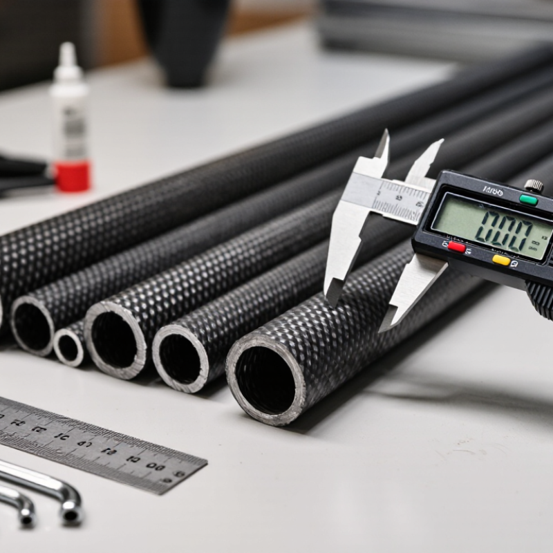
Define the load before comparing carbon fiber square rods. A rod carrying 300 newtons may need different dimensions for tension, bending, or compression. Note the force direction, contact points, and whether the load remains steady. Sudden impacts require additional allowance. In practical testing, I record the maximum force, not only the average reading. A safety factor is essential. Many designs use two or three times the expected working load, depending on risk and uncertainty.
Length strongly affects stiffness and buckling resistance. A 200-millimeter rod can feel rigid, while a 1,000-millimeter rod with the same profile may flex noticeably. Measure the unsupported length, not the total part length. Then estimate deflection under the real load. For compression, check the slenderness ratio carefully. A strong material can still buckle unexpectedly. This is where simple weight comparisons become misleading.
Shape requirements should match the movement and connection method. A square profile resists twisting and offers flat faces for clamps or bonded joints. However, sharp corners can experience local stress and surface damage. Check the outer dimensions, wall thickness, corner radius, and internal clearance. Solid and hollow sections behave differently. I once treated a hollow section like a solid one during an early estimate; the result was too optimistic. Allow space for fasteners, protective sleeves, and inspection. Small details matter.
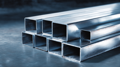
Choosing a carbon fiber square rod starts with its material system, not its appearance. Most rods use carbon fibers embedded in epoxy resin. Carbon fiber provides stiffness, while the resin holds the fibers together and transfers loads. Higher-strength fibers can reduce weight, but they may cost more and feel less forgiving during impact. Some applications use thermoplastic resin for improved toughness and faster processing. However, temperature resistance and bonding behavior must be checked carefully.
Layup controls how the rod behaves. A 0-degree layup places most fibers along the length, creating excellent bending stiffness. It suits beams, braces, and lightweight supports. A 0/90-degree layup adds strength across the square faces. This helps resist splitting and side loads. Quasi-isotropic layups include angled plies, such as 45 degrees, for better torsional performance. They usually weigh more. Small details matter.
In practical testing, I compare rods under bending, twisting, and clamp pressure. A rod with many longitudinal fibers may deflect less, yet crack near a drilled hole. A tougher mixed layup may survive handling better, even with slightly lower stiffness. I once assumed the stiffest sample was the best choice. That assumption failed when repeated twisting loosened its bonded joint. Check fiber direction, wall thickness, corner radius, and resin quality. Also request test data that matches your loading conditions, not only headline strength figures.
| Material and Layup | Typical Fiber Arrangement | Axial Tensile Modulus | Axial Tensile Strength | Typical Density | Axial Thermal Expansion | Bending and Torsional Behavior | Impact and Transverse Performance | Best-Suited Applications |
|---|---|---|---|---|---|---|---|---|
| Standard-Modulus Carbon Fiber Unidirectional Layup |
Approximately 80–95% of the reinforcing fibers run along the rod axis. | 100–160 GPa | 800–1,500 MPa | 1.50–1.65 g/cm³ | Approximately −0.2 to −0.6 × 10⁻⁶/°C along the fiber direction | Very high axial stiffness; limited resistance to off-axis bending, splitting, and torsion. | Lower transverse strength; more sensitive to point loading and edge damage. | Lightweight axial supports, tension members, guide rails, and straight structural rods. |
| Standard-Modulus Carbon Fiber 0°/90° Cross-Ply Layup |
Fibers are divided mainly between the axial direction and the transverse direction. | 70–130 GPa | 600–1,200 MPa | 1.52–1.68 g/cm³ | Approximately −0.1 to +2.0 × 10⁻⁶/°C, depending on the 0°/90° ratio | More balanced bending stiffness and improved resistance to side loads than a unidirectional rod. | Better transverse stability and reduced tendency to split along the length. | Square rods exposed to moderate lateral loads, frames, brackets, and machine components. |
| Standard-Modulus Carbon Fiber Quasi-Isotropic Layup |
Common angle sequence includes 0°, +45°, 90°, and −45° plies. | 55–100 GPa | 450–900 MPa | 1.55–1.72 g/cm³ | Approximately 0 to +4.0 × 10⁻⁶/°C | Balanced stiffness in multiple directions; good resistance to combined bending, torsion, and lateral loading. | Generally better damage tolerance and dimensional stability under multidirectional loading. | Robotic arms, instrument frames, structural brackets, and square rods with changing load directions. |
| Intermediate-Modulus Carbon Fiber Unidirectional Layup |
High proportion of axial fibers with a stiffer carbon-fiber grade. | 140–220 GPa | 900–1,700 MPa | 1.55–1.70 g/cm³ | Approximately −0.3 to −0.8 × 10⁻⁶/°C along the fiber direction | Higher axial rigidity than standard-modulus material, with low deflection under axial loading. | Transverse performance remains limited unless additional 90° or ±45° plies are included. | Precision shafts, long-span supports, low-deflection beams, and aerospace-style lightweight structures. |
| Intermediate-Modulus Carbon Fiber ±45° and 0° Balanced Layup |
Axial fibers are combined with ±45° fibers for shear and torsional load transfer. | 95–170 GPa | 700–1,400 MPa | 1.58–1.73 g/cm³ | Approximately −0.1 to +2.5 × 10⁻⁶/°C | Strong combined bending and torsional performance; lower axial stiffness than a mainly 0° layup. | Improved resistance to twisting, local cracking, and off-axis loads. | Drive mechanisms, rotating supports, robotic links, and square rods subject to torsion. |
| High-Modulus Carbon Fiber Unidirectional Layup |
Very high fraction of fibers aligned with the rod axis. | 180–300 GPa | 500–1,200 MPa | 1.55–1.75 g/cm³ | Approximately −0.5 to −1.2 × 10⁻⁶/°C along the fiber direction | Exceptional axial stiffness and low deflection; relatively brittle and less tolerant of impact or severe bending. | Lower strain-to-failure and greater sensitivity to transverse impact and stress concentrations. | Optical benches, metrology structures, precision positioning systems, and vibration-sensitive supports. |
| Carbon Fiber and Glass Fiber Hybrid 0°/±45° or 0°/90° Layup |
Carbon fibers provide axial stiffness while glass fibers improve strain capacity and impact tolerance. | 45–110 GPa | 500–1,200 MPa | 1.65–1.90 g/cm³ | Approximately 0 to +8.0 × 10⁻⁶/°C | Moderate axial stiffness with improved toughness and tolerance to handling damage. | Better impact resistance and transverse strength than an all-carbon unidirectional rod. | Protective structures, sports equipment components, general-purpose frames, and cost-sensitive applications. |
| Carbon Fiber Braided or Woven Layup | Interlaced fibers typically positioned near 0°/90° or ±45°. | 35–90 GPa | 300–800 MPa | 1.55–1.75 g/cm³ | Approximately 0 to +6.0 × 10⁻⁶/°C | Good multidirectional stability and torsional behavior; lower axial efficiency because fibers are not all straight. | Good resistance to handling damage, splitting, and localized surface impact. | Complex shapes, protective covers, short structural members, and applications requiring balanced directional properties. |
How to Choose the Right Carbon Fiber Square Rod?
Select the Right Dimensions and Surface Finish
Carbon fiber square rods should be selected from the load path, not appearance. Start with the unsupported length, bending direction, and expected load. A taller cross-section usually improves bending stiffness, while a larger section can increase torsional resistance. Check the rod’s wall construction, too. A hollow profile may reduce weight, but it can lose stability under compression. Small differences matter.
The 2024 Grand View Research report estimates the global carbon fiber market will grow at about 10% annually through 2030. This expansion increases product variety, but it also makes comparison harder. Do not rely on carbon fiber content alone. Request tensile, flexural, and compression data for the exact profile and fiber orientation. Values from a round rod cannot reliably predict a square rod’s performance.
Surface finish affects fit and handling. A smooth pultruded surface suits slides, guides, and visible assemblies. A lightly textured finish can improve adhesive bonding after proper cleaning and abrasion. Remove only the minimum material during sanding. Excessive sanding may expose fibers and weaken the corner. I have seen clean-looking edges fail early because the finish was treated as cosmetic. It is not. Check corner radii, dimensional tolerance, and straightness against the drawing. Measure several points, not one. Better still, test a short sample under the real mounting conditions.
Select the right dimensions and surface finish based on mass, stiffness, handling, and application requirements.
Larger square sections provide higher bending stiffness but add mass quickly. The values shown use a theoretical carbon fiber composite density of 1.6 g/cm³ and assume a solid square section.
Smooth: suitable for clean appearance and lower friction. Matte: helps reduce glare and is commonly selected for a technical appearance. Textured: can improve grip where the rod is handled.
Confirm the outside dimensions, length tolerance, fiber orientation, cut-end quality, and whether the finish is compatible with bonding, sliding, or clamping requirements.
A carbon fiber square rod should be chosen by its working conditions, not appearance alone. Strength describes how much load the rod can withstand before failure. Stiffness describes how much it bends under that load. Stiffness matters too. A rod may remain unbroken but still deflect enough to damage a mechanism or reduce accuracy.
Check the expected load, span, support points, and load direction. A longer rod usually bends more, even when its material strength remains unchanged. Measure the actual space available, because increasing the square section can improve bending resistance significantly. Weight also matters in moving assemblies, camera supports, and lightweight frames. Compare mass per meter rather than relying on a general “lightweight” claim. I have seen designs fail because engineers focused on strength and ignored excessive flex.
Durability depends on more than carbon fibers. Inspect the surface for scratches, crushed corners, and poorly finished ends. These small defects can become stress concentration points. Consider moisture, heat, ultraviolet exposure, vibration, and repeated loading. Carbon fiber resists fatigue well in many applications, but the resin and joints may limit service life. Test a sample under realistic conditions when possible. A simple dial indicator can reveal deflection that calculations overlook. Leave a sensible safety margin, especially when impacts or uncertain loads are involved. Perfect calculations are uncommon. Conservative testing is wiser.
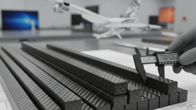
Manufacturing quality affects strength, fit, and service life. Inspect each face under bright, angled light. Look for pinholes, dry fibers, resin-rich streaks, and chipped corners. The rod should remain straight on a flat table. Small twists can create serious alignment problems. Ask for dimensional tolerances, fiber orientation, cure records, and test results based on ASTM D3039 or an equivalent standard. A certificate helps, but it does not replace inspection. I have seen attractive surfaces hide uneven walls.
Compatibility requires more than matching width and length. Check the working load, bending direction, temperature range, and fastening method. Carbon fiber conducts electricity, so contact with aluminum or steel may require an insulating layer. Confirm that the adhesive suits the resin system and expected temperature.
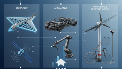
The U.S. Department of Energy reports that a 10% vehicle weight reduction can improve fuel economy by about 6–8%. That benefit depends on a reliable structure, not carbon fiber alone.
Cost should include cutting, drilling, shipping, rejects, and replacement risk. A cheaper rod may have wider tolerances or inconsistent fiber content. The 2024 CompositesWorld State of the Industry report describes continued demand for lightweight composite structures across transportation and industrial applications. Demand does not guarantee quality.
Compare price per usable meter, not price per piece.
A simple trial order can reveal fit, surface damage, and repeatability before a larger purchase. My first estimate is often too optimistic. Safety margins deserve a second review.