- Home
- Products
- About Us
- News
- Blog
- Video
- Contact
Leave Your Message
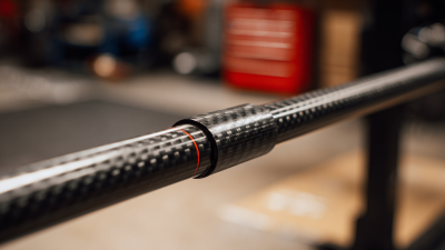
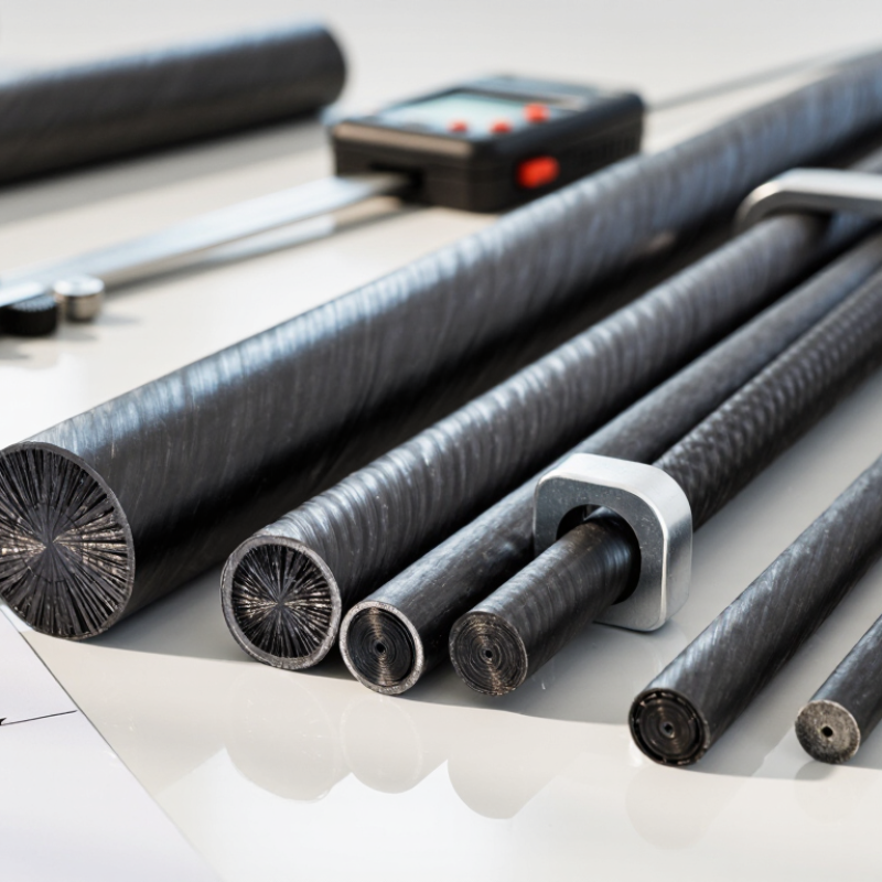
Choosing a Pultruded Carbon Fiber Rod is not just a matter of picking the stiffest option. Diameter, fiber orientation, resin system, and manufacturing tolerances all affect performance. A rod supporting a camera mast faces different demands from one used in a lightweight frame. Measure the load, unsupported length, and working environment before comparing product specifications.
The U.S. Department of Energy’s Vehicle Technologies Office reports that reducing vehicle weight by 10% can improve fuel economy by roughly 6% to 8%. That figure concerns vehicles, not every rod application, but it shows why engineers value lightweight structures. For a specific design, compare the rod’s tensile strength, flexural stiffness, and density with the actual load case. ASTM D3917 provides dimensional-tolerance specifications for pultruded reinforced-plastic rods, bars, and shapes. Ask suppliers for test data and tolerance details, rather than relying on a headline strength value alone.
Details matter. A close-fitting rod may need tighter diameter tolerances; a long exposed span may need greater stiffness to limit deflection. Check resin compatibility, temperature range, surface finish, and how the rod will be cut or joined. I still find one point easy to miss: published values may come from different test methods, so they are not always directly comparable. There is no universal best rod. A careful selection balances measured performance, fit, and service conditions—and leaves room to question incomplete data.
How to Choose a Pultruded Carbon Fiber Rod
Define the Application Requirements for a Pultruded Carbon Fiber Rod
Start with the loads the rod must carry. Record peak force, load direction, unsupported length, and expected cycles. Pultruded rods are strongest along their fibers, so transverse loads and drilled holes need special attention. Small details matter. A rod that survives a straight pull may still buckle or split when clamped.
Set measurable limits for deflection, weight, diameter, and length. The U.S. Department of Energy’s 2016 report, Carbon Fiber Composites: Enabling a Sustainable Energy Future, describes potential component weight reductions of up to 50% compared with steel. Treat that as a broad design opportunity, not a guaranteed saving for a particular rod. Geometry and loading change the result. Ask suppliers for longitudinal tensile and flexural properties, test methods, and dimensional tolerances.
Then define the operating environment. Note temperature swings, moisture, UV exposure, chemicals, and contact with metals. Specify how the ends will be attached; tight clamps can crush a thin-walled rod. Include acceptable bending, inspection frequency, and service life. A practical first specification may still be incomplete. Review it against a prototype under realistic loads, especially if the rod sees impacts or side loading.
| Requirement | What to Define | Useful Units or Input | Selection Guidance |
|---|---|---|---|
| Primary function | Describe whether the rod acts as a tension member, compression strut, support, guide, or bending element. | Application description and load direction | Pultruded rods are strongest and stiffest along the fiber direction. Confirm that the principal load follows the rod’s length. |
| Applied loads | Specify maximum and typical tensile, compressive, bending, and shear loads, including impact or cyclic loads where applicable. | N, kN, N·m, cycles | Distinguish steady loads from peak loads. Check compression members for buckling, not only material strength. |
| Rod dimensions | Set the required diameter, overall length, straightness, and any cut-length or fit requirements. | Diameter and length in mm; tolerances in mm | Use a drawing to specify dimensions and tolerances. Confirm that the supplier’s available sizes and tolerance capability meet the design. |
| Stiffness and deflection | Define the maximum permitted axial extension or lateral deflection under the specified load and support conditions. | Deflection in mm; axial stiffness in N/mm if specified | Evaluate stiffness using the rod’s length, cross-section, loading, and supplier-provided longitudinal modulus. Do not assume a universal modulus. |
| Support and end conditions | Document how the rod is supported and how loads enter at each end, including unsupported length and joint geometry. | Support spacing in mm; joint dimensions in mm | End constraints affect deflection and buckling. Design clamps or bonded joints to avoid crushing, splitting, or concentrated transverse loads. |
| Load direction and transverse stresses | Identify side loads, bearing pressure, holes, notches, and any loads perpendicular to the rod axis. | N, MPa, contact area in mm² | Carbon fiber composites are direction-dependent. Transverse and interlaminar behavior can differ substantially from axial behavior. |
| Operating environment | State minimum and maximum temperatures, moisture exposure, UV exposure, chemicals, and outdoor or indoor use. | Temperature in °C; exposure duration and conditions | Verify resin-system limits and environmental compatibility for the specific rod. Temperature limits depend on the product and its resin. |
| Electrical and surface requirements | Specify electrical isolation or conductivity needs, surface finish, coating, and cosmetic requirements. | Surface specification; electrical requirement | Carbon fibers are electrically conductive. Add suitable insulation or protective finishing when the application requires it. |
| Safety factor and service life | Set the design factor, expected service duration, inspection interval, and consequences of failure. | Design factor; hours, cycles, or years | Choose the factor based on load uncertainty, fatigue, impact, environment, and applicable design rules; validate critical designs by testing. |
| Verification and documentation | Define required certificates, test data, dimensional inspection, traceability, and acceptance criteria. | Inspection plan and test acceptance limits | Request product-specific data for axial properties, dimensions, and environmental limits. Values should match the actual rod construction. |